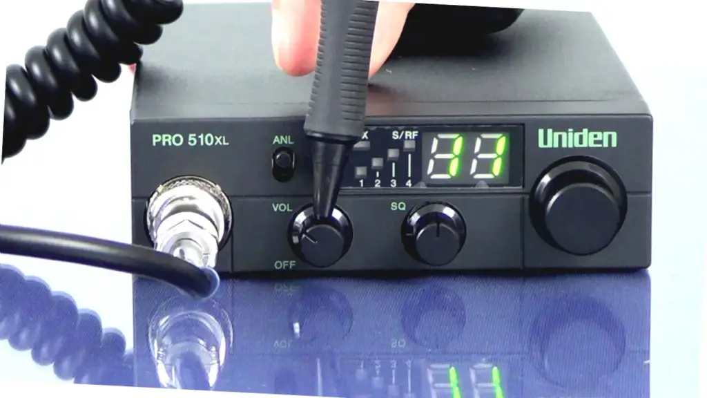
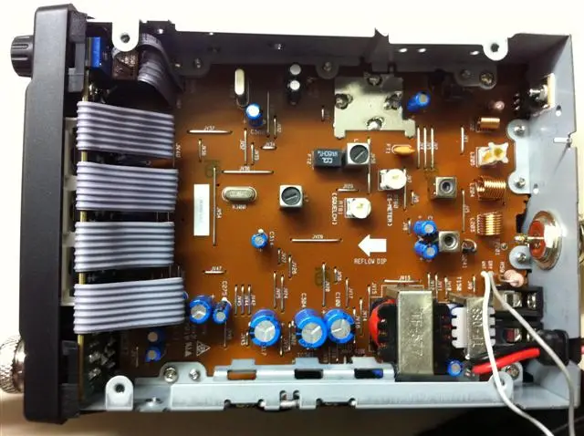
Uniden Pro 510 XL Mods include the Power tweaking mod, the wide bandwidth direct RF modulation mod and the 24V power supply mod. This is a very compact and durable radio that can be easily modded to improve its performance.
Do you still have questions about the Uniden Pro 510 XL Mods? Do not worry. Read this article to find out more about different Uniden Pro 510 XL Mods.
What Are Some Common Uniden Pro 510 XL Mods?
Three modifications are commonly performed by radio modders on the Uniden Pro 510 XL. here are those three mods in brief:
| Uniden Pro 510 XL Mods | Purpose | Difficulty level |
| Power tweaking mod | Maximizing the forward power. | Easy |
| Wide bandwidth direct RF modulation mod | 1. Excellent square wave response up to more than 250 KHz. 2. Increased precision in duty cycle control. | Moderate |
| 24 V power supply mod | Increase the peak power level to 20 to 22 W. | Hard |
Are you confused about how to perform these mods on your Uniden Pro 510 XL? In the section below I will go through all the modding processes in detail.

How to Perform Uniden Pro 510 XL Mods?
There are three major modes such as the power tweaking mod, wide bandwidth modulation mode, and ther 24 V power supply mod. Just like the uniden pro 510xl, the uniden grant xl has some mods too. Alright, so let’s explore them in detail.
Power tweaking mod:
Tools Needed:
- A 0.47 Ohm resistor
- A soldering iron
- An oscilloscope
Modding Process:
Here are the steps you should follow if you want to do the power tweaking mod:
Step 1: Locate a 2.7 Ohm resistor on the pcb of the radio set. You will find it in front of the 15 Ohm final bias resistor.
Step 2: Replace the 2.7 ohm resistor with a 0.47 Ohm resistor.
Step 3: Retune the L9,L6,L5 and L4 legs.
Step 4: Keep tuning until the forward power of the radio is maximized.
Congratulations! Your power tweaking mod is not complete.
Wide Bandwidth Modulation Mod:
Tools Needed:
You will be needing these tools for the modding process:
- A 2N3904 NPN small-signal transistor. Try getting one with at least half an inch of leg on both sides for convenience.
- A 1N4148 silicon diode. Alternatively, you could also use a 1N914 switching diode.
- A resistor with a resistance of 10 K Ohm.
- A 35 V 470 microFarad electrolytic capacitor. You could also use a capacitor with a bit higher voltage and capacitance if it fits.
- A screwdriver.
- A soldering iron along with some solder
- A long 20 gauge or 22 gauge wire
- Small ferrite beads
Modding Process:
Now, follow these steps to mod the Uniden Pro 150 XL radio for a wider bandwidth modulation:
Step 1: Firstly, use the screwdriver to unscrew all the screws from the front and the back cover of the radio.
Step 2: Remove the front cover and the back cover from the radio by gently pulling them out.
Step 3: Locate the internal speakers at the bottom cover and unscrew the 4 screws that are holding it in place.
Step 4: Cut the wires that lead to the pcb from the internal speakers.
Step 5: Completely cut off the speaker wires. Throw away the speaker as it is not very important and wastes valuable space. The Uniden Pro 510 XL is already very small in size.
Step 6: Now, put the radio in an upside down position. The front side of the radio should be faced towards you.
Step 7: Locate the 5% 27 Ohm resistor. You will find it at the lower left hand side corner of the radio. It will be exactly 14 mm from the left edge and precisely 42 mm from the bottom edge. If you are not sure how to identify the resistance of the resistor, it will be colored red, violet, black and gold. The color code on the resistance will be in that order.
Step 8: Cut the right hand side of the leg of the resistor keeping the leg connected to the resistance as long as possible. You could also desolder the leg from the bottom of the pcb.
Step 9: Then locate the L2 transformer. You will find it near the 27 Ohm resistor further away from the lower edge. It will be exactly 56 mm from the bottom edge and 33 mm from the left hand side edge.
Step 10: Power up the soldering iron if you haven’t already.
Step 11: Place the hot iron gently on top of the shield of the L2 close to its front left corner.
Step 12: Putsome solder at the heated spot.
Step 13: Take the 2N3904 and hold it with your hand horizontally. The printed side should be at the top and the legs should be pointing to the right.
Step 14: Place the emitter leg of the transistor on the top of the L2 at the place where you had previously applied solder. Hold it until the solder cools and hardens.
Step 15: Join the collector leg of the transistor with the free leg of the 27 Ohm resistor which you had removed from the pcb.
Step 16: Solder the two legs together. Hold the legs until the solder hardens.
Step 17: Heat up the soldered spot of the L2 transformer.
Step 18: Take the 1N4148 diode or the 1N914 switching silicon diode.
Step 19: Solder the anode of the diode to the L2 transformer.
Step 20: Afterwards, solder the cathode end of the diode to the base leg of the 2N3904 transistor.
Step 21: Take the 10 K Ohm resistor.
Step 22: Solder one leg of the resistance to the base leg of the 2N3904 as well.
Step 23: Solder the 6 inch wire to the other leg of the resistance.
Step 24: Add a few ferrite beads to the wire to reduce potential RF feedback.
Step 25: Locate the TF 375 audio transformer on the pcb. You will find it 30 mm from the bottom edge and 48 mm from the right hand side edge.
Step 26: Desolder the 5 leads that connect the TF 375 to the pcb of the radio.
Step 27: Remove the two metal tabs that hold the transformer to the metal frame of the set..
Step 28: Take out the transformer from the set.
Step 29: Short the left rear transformer hole with the middle of the three front transformer holes.
Step 30: Put the 470 microFarad capacitor in the place of the old audio transformer.
Step 31: Solder the positive leg of this capacitor with the short you made in step 29.
Step 32: Solder the negative lead of the capacitor to the ground foil at the bottom. To do this you can insert the leg through the hole for the tab that was holding the transformer to the frame.
Step 33: Now flip the radio set so that the front of the radio is facing you.
Step 34: Locate the 2 screws at the right which are completely covered in copper foil with many gaps.
Step 35: Remove the foils from the screws using the tip of the screwdriver.
Step 36: Short the gaps around the screws using the wire..
Step 37: Reassemble the radio. Put back the covers at the front and at the back.
The wide bandwidth direct RF modulation mod is now complete.
Remember that this mod can reduce the power output from a maximum of 16 Watts to about 4 Watts. Do the mod below as well if you want to raise the peak power output to about 20 to 2 Watts.

24 V Power Supply Mod:
With this mod you can include a 24 V external power supply to the Uniden Pro 510 XL.
Tools Needed:
You need the same tools that you used in the Wide bandwidth direct RF modulation mod. You also need:
- A 24 V external power supply
- An 18 gauge wire.
Modding Process:
Follow these steps to do this Uniden Pro 510 Xl mod:
Perform the first 28 steps of the wide bandwidth direct RF modulation mod.
Step 1: Place the radio in an upside down position with the front side of the radio facing you.
Step 2: Take the 24 V external power supply.
Step 3: Solder the positive lead of the 24 V power supply to the left of the two rear holes of the transformer. You can use the 18 gauge wire for this purpose.
Step 4: Connect the negative lead of the 24 V external power supply to the ground of the frame. Solder the connection.
Step 5: Locate the D7 diode on the pcb. You will find right next to the left and rear of the former location of the audio transformer.
Step 6: Place the 470 microFarad in the place where the now removed audio transformer used to be.
Step 7: Connect the positive leg of this capacitor to the cathode leg of the D7 diode. The cathode leg can be identified using the black bad mark. Solder the two legs.
Step 8: Solder the negative leg of the capacitor to the ground foil at the bottom side of the radio.
Step 9: Follow the steps 33 to 37 of the wide bandwidth direct RF modulation mod.
Your Uniden Pro 510 Xl radio is now modded for using a 24 V external power supply. In some country performing these may be illegal. So ensure these mods are legal in your country to avoid legal trials. Also, improper modding may cause damages like frequency not transmitting, reduced range, interference, safety issues, etc.
Frequently Asked Questions (FAQs):
How many Watts of RF output is a Uniden Pro 510 xl?
The Uniden Pro 510 XL has a RF output of 4 watts. This means the Uniden Pro 510 XL has a range of about 3 miles or 4.8 Km to about 20 miles or 32 Km. But ultimately the range of the radio will depend mostly on the terrain.
What frequency is the Uniden Pro 510xl?
The frequency of the Uniden Pro 510 XL is 26.965 MHz to 27.504 MHz. This particular CB radio operates on 40 channels by default. This model comes with a +/- 0.005% frequency tolerance. It is a very compact radio with only the most essential features.
What is the busiest CB channel?
CB channel 19 is the busiest of all CB channels. It is commonly used by truckers for small distance communication. The channel 17 is another busy channel used by truckers. Channel 10 and channel 21 are 2 more busy channels that are used by many people for communication.
Conclusion
Now you know about the Uniden Pro 510 XL mods. These CB radios are very compact and durable. By modding them you can improve the power and quality of the signal. This radio is very popular among the amateur radio community. I hope that this article managed to answer all your questions about modding this particular radio set.
That is all for today. Thank you and Goodbye!
